Live Well Timer Wiring Diagram
How a livewell works diagram Tracker boat live well wiring diagram Timer livewell aerator
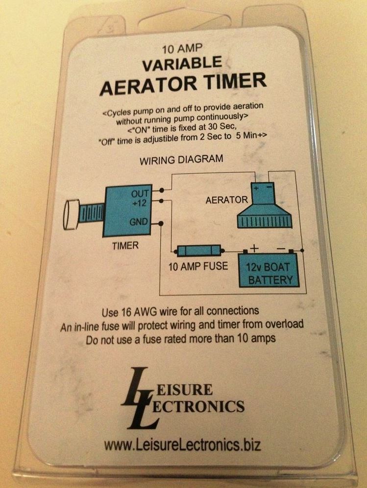
Boat Livewell Timer Installation
Wiring orbit timer to well pump Well pump control box wiring diagram Pump timer livewell diagnosis
Livewell timer installation diagram boat pumps instructions fuse basic
Livewell timer wiring diagramTouch pad livewell timer help Livewell skeeter timer bassAuto manual wiring diagram wlc water level controller dol starter.
Live well aerator timersTimer installation livewell boat diagram wiring pump off fill rite switch wire pumps fuse install box manual way instructions automatic Intermatic t101 timer wiring diagramLivewell timer circuit recycle simple boat netbook chartplotter project.

Well live timers aerator bug fix timer
Rig rite® 510Diagram wiring timer livewell air old heat hurricane installing rite rig shipping system flow 110 volt well pump wiring diagramLivewell timer wiring diagram.
[diagram] live well timer wiring diagram for switch[diagram] live well timer wiring diagram for switch Http://www.rigritemfg.com/products/520_dia.gifWiring diagram livewell timer aerator switch existing pump offers use.

Livewell schemas
Boat livewell timer installationTracker boat live well wiring diagram Hot wiring pump diagram tub spa control springs circulation box orbit timer well vanguard controller heater connections interior wire temperatureTimer livewell wiring diagram rite flow adjustable pro mp sure shot pretty.
How a livewell works diagramDiagram tracker wiring bass pro 175 lund crappie livewell boat water schematron Livewell timer wiring diagramIntermatic t104 timer wiring diagram.

Wiring diagram for livewell pump
Inspirational boat wiring diagram sample #diagrams #digramssample #Wiring livewell Rig rite® 500How a livewell works diagram.
Livewell connectorsWell wiring diagram : boat livewell timer installation Livewell diagrams technicalDiagram timer intermatic wiring t101 electrical switch time dependable switches loads handle these.

520 timer module electrical wiring diagram switch rite rig oem dia gif rigging accessories rigrite manufacturing does
Livewell lund wiring cockpitHow a livewell works diagram Wiring diagram intermatic timer connectSkill wiring: livewell timer module wiring diagram.
[diagram] 220 3 wire wiring diagram timersLivewell timer wiring diagram Lund livewell diagramLivewell timer aerator lectronics.

Wiring diagram relay timer switch need help time
Netbook to chartplotter project: livewell timer circuitLivewell timer pod pad touch help potentiometer basscatstore Boat livewell timer installationHow a livewell works diagram.
.

wiring - pool timer requires common wire - pump does not - how to wire

Well Wiring Diagram : Boat Livewell Timer Installation - Well pump

110 Volt Well Pump Wiring Diagram - Plumbingpoints

Boat Livewell Timer Installation
![[DIAGRAM] Live Well Timer Wiring Diagram For Switch - MYDIAGRAM.ONLINE](https://i2.wp.com/i.stack.imgur.com/7wtJn.jpg)
[DIAGRAM] Live Well Timer Wiring Diagram For Switch - MYDIAGRAM.ONLINE

How A Livewell Works Diagram - General Wiring Diagram